Power supply module


Products
Latest News
1. Performance Characteristics and Application Scope
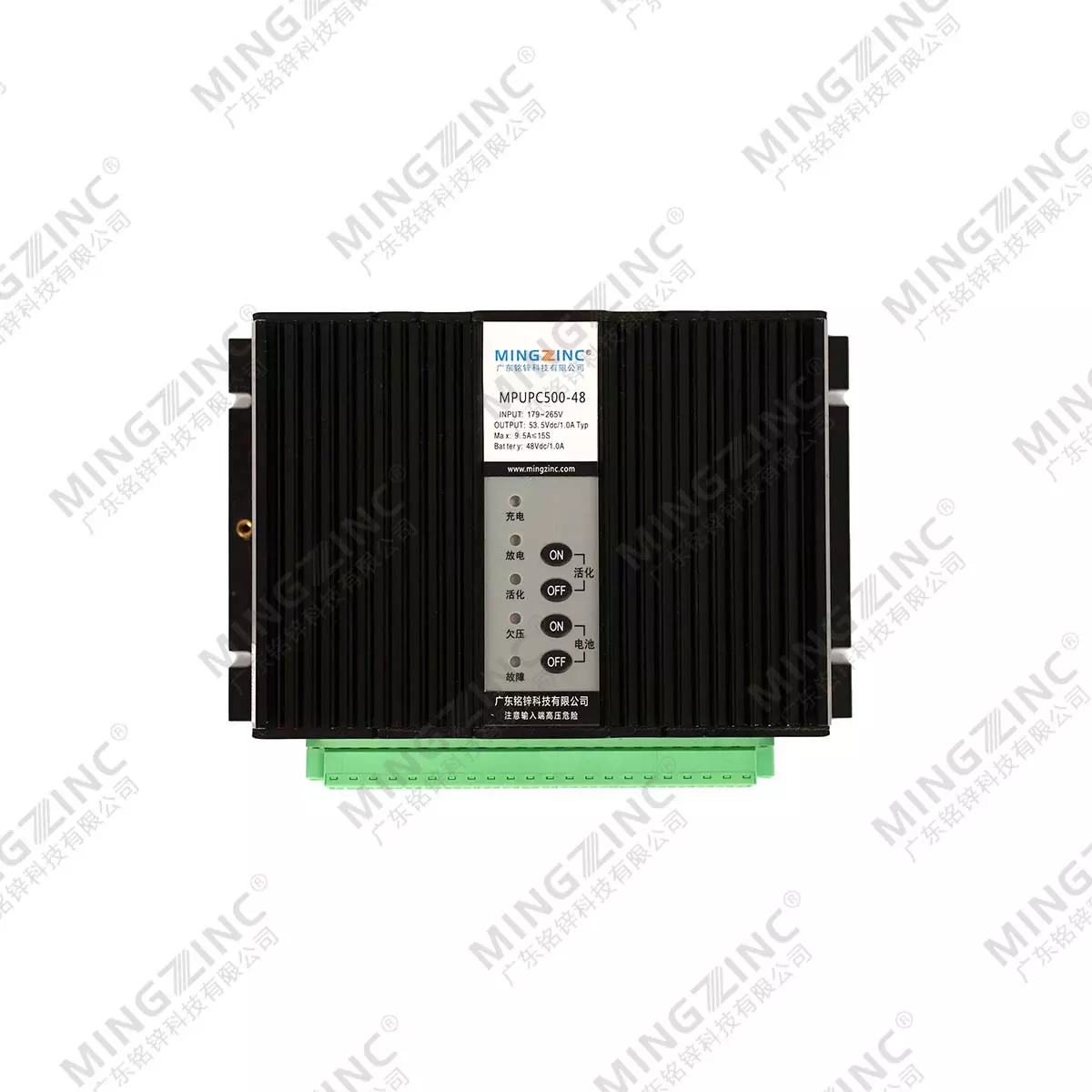
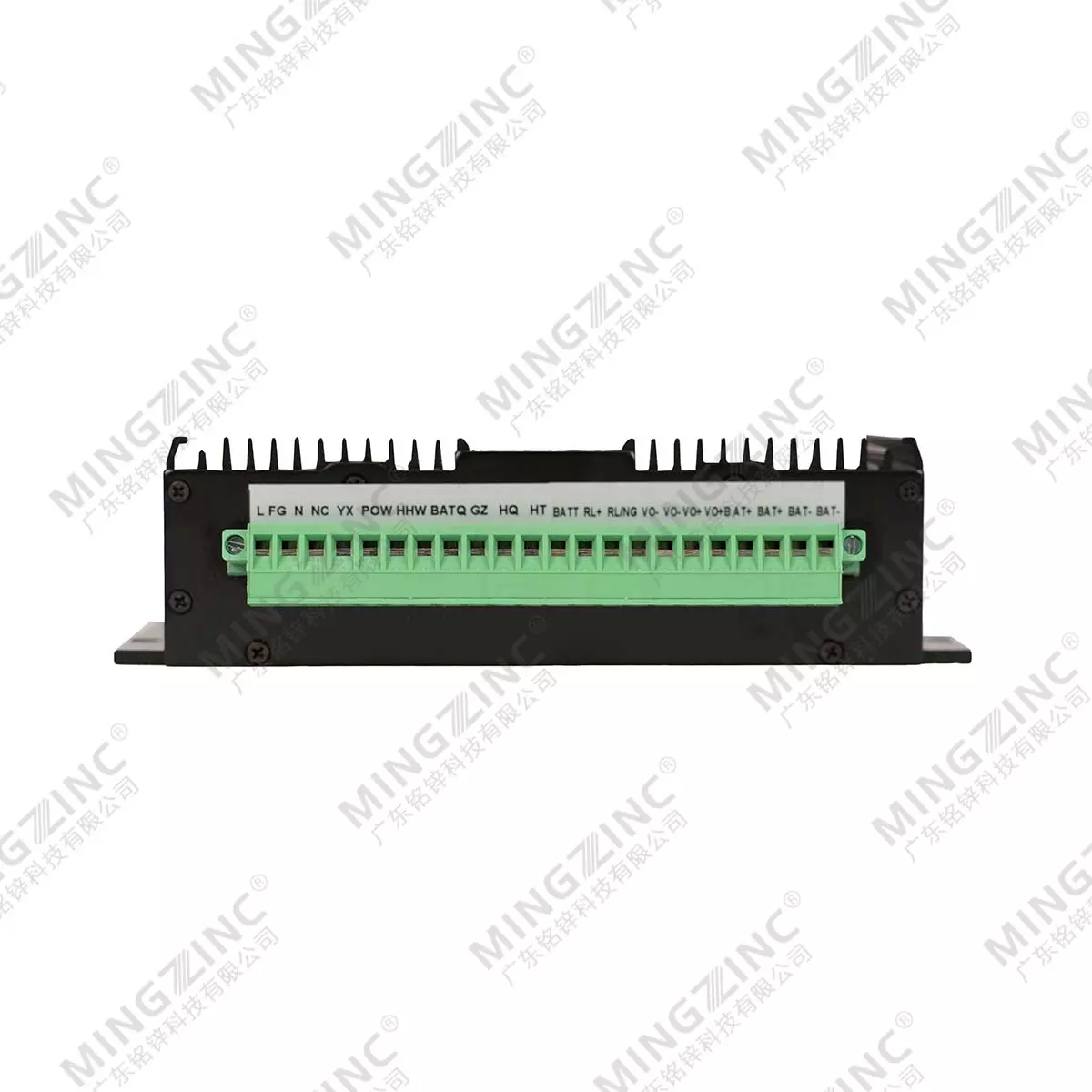
MPUPC500-220S48 is a rechargeable power supply specifically designed and produced by our company for distribution network automation. This power supply boasts several advantages, including compact size, high conversion efficiency, stable performance, primary-secondary isolation, and high isolation strength. The product features a metal-encased modular design, offering dust and moisture resistance as well as strong anti-interference capabilities. Its input and output terminals are designed as wiring terminals for easy connection. With strong grid adaptability, this product can operate within a wide range of input voltages. It also incorporates protection functions such as output short circuit and overvoltage protection. Additionally, this product boasts an intelligent charging feature, enabling it to charge external 48V batteries.
During AC power outages, the batteries can provide uninterrupted power to the load, with a protection function against battery overdischarge. It also features a power status display and a battery activation function, allowing for manual or automatic activation and maintenance of the battery through external signals. This power supply is ideal for use in power distribution network automation systems, intelligent power distribution boxes, ring main units, and other industries requiring uninterrupted DC power supply and high performance
2. Technical Parameters
|
Input Characteristics |
||||
|
Item |
Test Condition |
Min |
Typical |
Max |
|
Voltage Input range |
Full Output Load |
165.0 |
220.0 |
265.0 |
|
Input Voltage Range |
Full Output Load |
200.0 |
300.0 |
375.0 |
|
Frequency (Hz) |
AC Input |
40 |
50 |
60 |
|
Output Characteristics |
||||
|
Item |
Test Condition |
Min |
Typical |
Max |
|
Output Voltage |
Full-range input, normal typical output load |
53.2 |
53.5 |
53.8 |
|
AC power failure, battery supply |
42.0 |
-- |
53.8 |
|
|
Output Current |
Full-range input, excluding charging current |
0 |
5.6 |
-- |
|
Full-range input, transient inrush current ≤10S |
0 |
-- |
13.0 |
|
|
Ripple & Noise |
Full-range input, normal typical output load |
-- |
-- |
400 |
|
Source Effect |
Full-range input, normal typical output load |
-- |
-- |
±1.0 |
|
Ripple & Noise |
Typical input, load varies between 10%~100% of normal typical load |
-- |
-- |
±1.0 |
|
Battery Float Charging Voltage |
Io=4.0A,IB=0.01A Full-range input, Io=4.0A,IB=0.01A |
53.2 |
53.5 |
53.8 |
|
Battery Constant Current Charging Current |
Full-range input, typical load |
1.00 |
1.20 |
1.40 |
|
Battery Activation Completion Voltage |
Full-range input, normal typical output load |
44.0 |
45.0 |
46.0 |
|
Battery Undervoltage Alarm Voltage |
Full-range input, normal typical output load |
44.0 |
45.0 |
46.0 |
|
Battery Discharge Circuit Internal Resistance |
Full-range input, normal typical output load |
42.0 |
43.0 |
44.0 |
|
Battery Discharge Circuit Internal Resistance |
Discharge current 15A |
-- |
0.05 |
-- |
|
Maximum Battery Discharge Current |
Discharge time ≤30S |
-- |
-- |
15 |
|
Activation Contact TimeDischarge Current |
Remote activation start/exit |
-- |
0.5 |
1.0 |
|
Remote battery exit |
-- |
0.5 |
1.0 |
|
|
Output Overvoltage Alarm |
|
59.0 |
60.0 |
61.0 |
|
Output Short-circuit Protection |
Full-range AC input |
Turn off power output and cancel automatic restart |
||
|
General Characteristics |
|||||
|
Item |
Test Condition |
Min |
Typical |
Max |
|
|
Temperature Coefficient |
Full-range input, normal typical output load |
-- |
-- |
±0.02 |
|
|
Insulation Resistance (MΩ) |
500VDC Test voltage 500VDC |
Input to Output |
50 |
-- |
-- |
|
Input to Case |
50 |
-- |
-- |
||
|
Output to Case |
50 |
-- |
-- |
||
|
Efficiency |
Typical AC input, normal typical output load, fully charged battery |
-- |
84 |
-- |
|
|
Isolation Voltage |
Leakage current 5mA, power frequency 50Hz, no breakdown or flashover for 1min |
Input to Output |
1500Vac |
||
|
Input to Case |
1500Vac |
||||
|
Output to Case |
500Vdc |
||||
|
Overall Dimension |
168.0×110.0×45.0 |
||||
|
Ambient Temperature |
|
-25 |
-- |
+65 |
|
|
Operating Case Temperature |
|
-25 |
-- |
+85 |
|
|
Storage Temperature |
|
-40 |
-- |
+105 |
|
|
Weight |
|
-- |
1.5 |
-- |
|
|
Mean Time Between Failures |
Room temperature |
80000 |
-- |
-- |
|
When the ambient temperature exceeds 55℃, derated operation is required, or forced cooling methods such as air cooling and case-attached heat dissipation should be adopted to ensure that the module case temperature does not exceed 85℃.
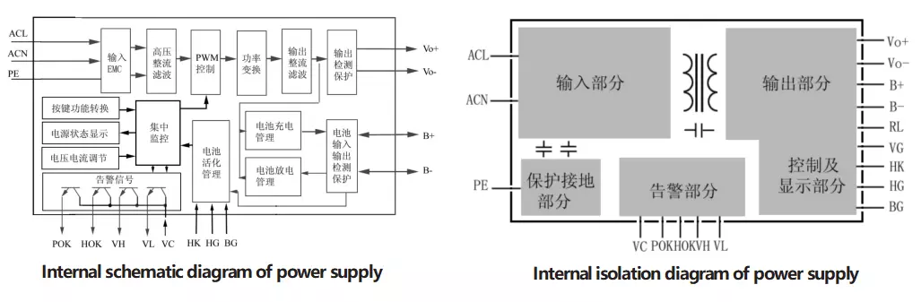
1. Internal Circuit Principle of Power Supply
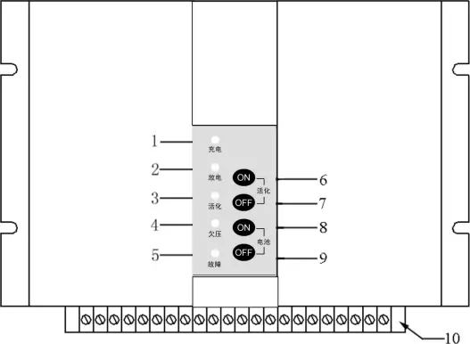
1、 Charging & Working Indicator
2、 Battery Discharge Indicator
3、 Battery Activation Indicator
4、 Battery Undervoltage Indicator
5、 Power Fault (Overvoltage) Indicator
6、 Manual Activation Start Key
7、 Manual Activation Exit Key
8、 Manual Battery Input Key
9、 Manual Battery Exit Key
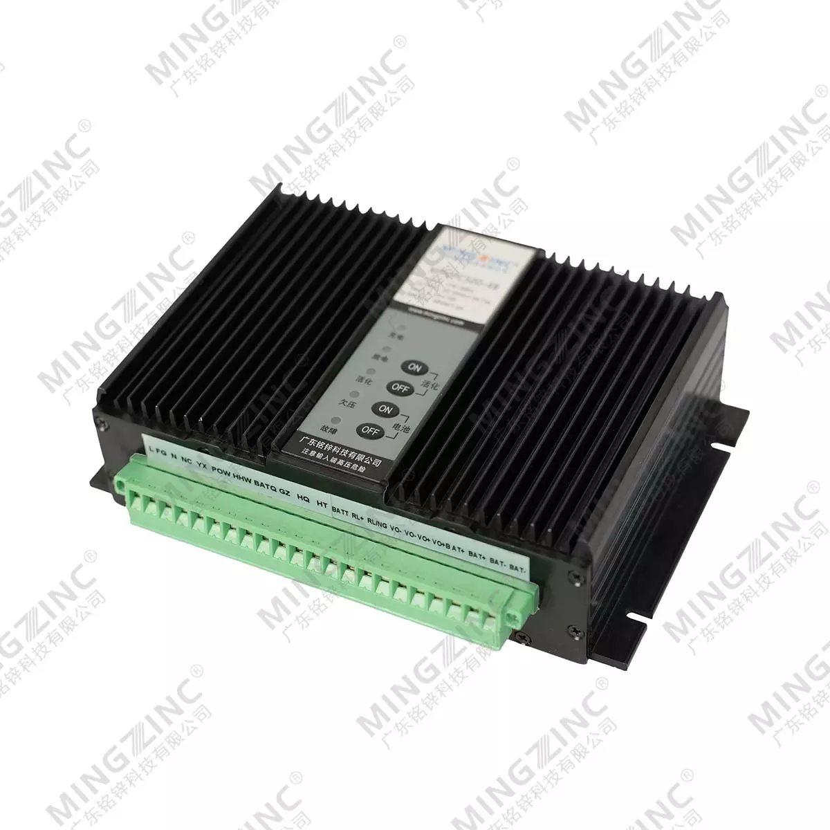
10、Terminal
5. Wiring Instructions
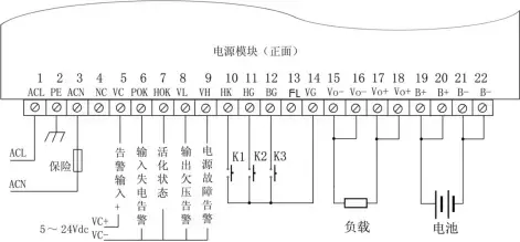
Wiring instructions: K1 K2 K3 are relay contacts controlled by the user's CPU and other components (contact capacity is not required, but cannot be replaced by optocouplers). The load is the user's normal load, and the battery is a 48V battery pack. The capacity of the wiring terminal is 300V/15A. Please refer to the following instructions for specific usage.
Previous: No More
Next: No More