



200W Isolated 110V to 24V DC-DC Converter for Railway Onboard Equipment
Why Do 24V Auxiliary Devices in 110VDC Railway Systems Experience Resets, Dropouts or Unstable Operation?
Railway vehicles may use a 110VDC power architecture, while onboard communication, monitoring, control and auxiliary electronics often require stable 24VDC power.
For engineers, the real challenge is not simply:
“How do I convert 110VDC to 24VDC?”
The more important question is:
Will the 24V electronics remain stable when the 110VDC bus changes, loads switch or electrical interference occurs during vehicle operation?
An unstable auxiliary power path may result in:
unexpected communication device resets;
monitoring equipment dropouts;
gateway or controller communication errors;
unstable data acquisition;
intermittent faults under specific operating conditions.
Intermittent problems are particularly difficult because engineers may spend significant time troubleshooting communication, wiring or software before identifying the power supply as the cause.
Why Is 110VDC Onboard Power Conversion Challenging?
1. A 110VDC bus does not always remain at exactly 110V
Battery condition, charging and discharging, and changing onboard loads can affect the actual DC bus voltage.
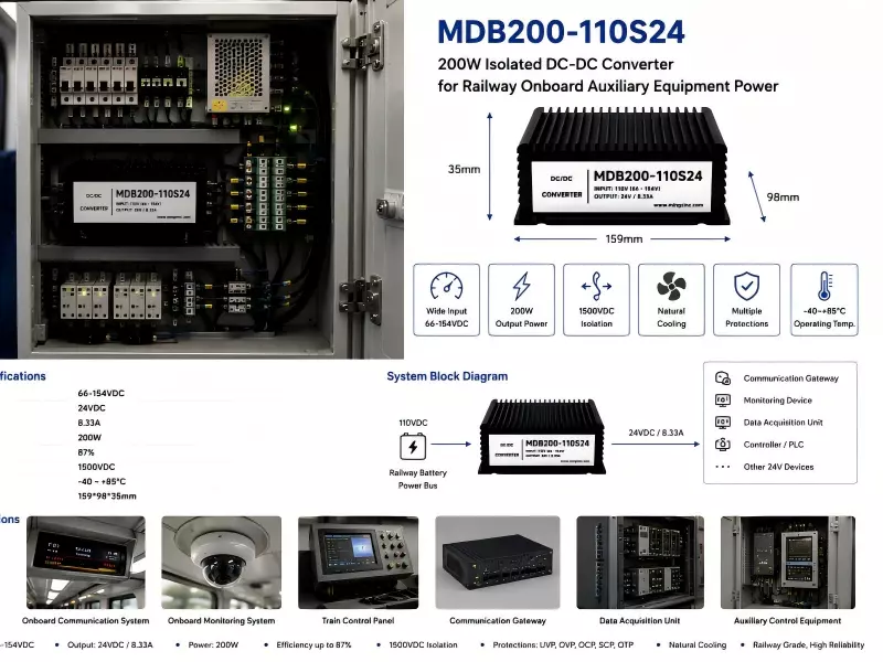
MDB200-110S24 accepts a 66–154VDC wide input range, allowing it to accommodate variations in the 110VDC power system while providing stable 24VDC output.
2. Communication and control electronics are sensitive to power interference
Railway vehicles contain multiple electrical systems and power paths.
Electrical disturbances from the input side may affect sensitive downstream electronics if the auxiliary power architecture is not properly designed.
MDB200-110S24 uses an isolated DC-DC architecture to create electrical separation between the 110VDC input domain and the 24VDC auxiliary power domain.
This helps reduce interference coupling and ground-related problems.
3. Multiple 24V devices require practical power capacity
A single auxiliary power node may supply:
communication gateways;
monitoring devices;
data acquisition units;
controllers;
other 24V auxiliary electronics.
The 200W power level provides practical capacity for multi-device onboard applications.
4. Onboard equipment operates under demanding conditions
Unlike equipment installed in a stationary control room, onboard electronics may experience vibration, temperature changes and continuous operation.
Engineers therefore need more than the correct voltage conversion.
They need a power solution designed around the actual operating environment.
How Does MDB200-110S24 Solve the Problem?
A dedicated 24V auxiliary power path can be created:
110VDC Railway Battery Bus
↓
66–154VDC Input
↓
MDB200-110S24 Isolated DC-DC Converter
↓
Stable 24VDC Auxiliary Power
↓
Communication / Monitoring / Gateway / Controller
The wide input range accommodates variations in the upstream 110VDC bus.
Galvanic isolation creates a separate power domain for downstream 24V electronics, helping reduce electrical interaction between the main power system and sensitive loads.
The 200W power level also provides practical capacity for multiple auxiliary devices operating simultaneously.
Why MINGZINC?
MINGZINC develops industrial isolated DC-DC power solutions around actual equipment operating conditions rather than voltage conversion alone.
For railway and onboard equipment projects, our engineering approach focuses on:
wide input voltage capability;
galvanic isolation;
EMI/EMC-resistant design;
stable output under load changes;
thermal management;
mechanical reliability for demanding environments;
electrical protection.
For OEM/ODM projects, input range, output parameters, interfaces, mounting and thermal solutions can also be adapted to specific equipment requirements.
Instead of forcing the application to fit a fixed standard converter, the power solution can be matched to the project.
What Value Does This Create for Engineers?
MDB200-110S24 creates a stable and isolated 24V auxiliary power domain between the 110VDC main bus and downstream electronics.
This can help engineers:
Reduce device resets caused by DC bus variations;
Reduce power-related communication problems;
Support multiple 24V auxiliary devices;
Simplify 110VDC-to-24VDC power architecture;
Reduce intermittent power-related faults;
Reduce field troubleshooting and maintenance;
Improve long-term onboard equipment reliability.
Typical Power Architecture
110VDC Railway Battery / Power Bus
↓
66–154VDC Input
↓
MDB200-110S24 Isolated DC-DC Converter
↓
Stable 24VDC Auxiliary Power
↓
Communication Gateway / Monitoring / Data Acquisition / Controller / Auxiliary Electronics
Recommended Application
Railway Onboard Auxiliary Equipment Power
Suitable for railway onboard communication equipment, monitoring systems, communication gateways, data acquisition devices, controllers and other onboard electronics using a 110VDC power bus with 24VDC auxiliary loads.
For Power Supply Distributors, Railway Equipment Suppliers, System Integrators and Railway Equipment OEMs, MDB200-110S24 can provide an isolated 24V auxiliary power solution for 110VDC systems, with OEM/ODM customization available for specific equipment requirements.
Previous: 150W Isolated 110V to 12V DC-DC Converter for Railway Communication Equipment
Next: No More